Dispensing Thermally Conductive Paste– The Hot Spot Solution Application
The application of dispensing thermally conductive paste is a key technology for solving the “hot spot” problem in electronic devices. Below, I will systematically explain it to you, including its principles, solutions, application cases, and best practices.
1.Core Concept: Why Apply Thermally Conductive Paste? — From “Surface Heat Dissipation” to “Precision Heat Dissipation”
Traditional methods of applying thermal paste using scraping or manual application have several problems:
● Uneven Thickness: Easily creates areas of varying thickness, affecting overall heat transfer efficiency.
● Air Bubbles: Manual application easily introduces air, forming insulating bubbles.
● Inability to Handle Complex Structures: Difficult to achieve uniform coverage for chips with inconsistent heights or areas containing components.
The core advantages of thermal paste application technology lie in its precision, controllability, and automation. It can:
1.Precise Positioning: Accurately apply thermal paste above heat sources (such as CPUs, GPUs, and power chips).
2.Controlled Dosage:Precisely calculate and control the amount of paste applied based on chip size and heat dissipation, achieving optimal thermal layer thickness.
3.Complex Pattern Coverage: Through programming, it is possible to draw “X” shapes, multi-dot multi-row patterns, grid shapes, and even custom shapes, ensuring complete coverage without air bubbles.
Ⅱ.Hot spot Solutions: How to Achieve Efficient Heat Dissipation Through Dispensing?
For “hotspots” (areas where the local temperature is significantly higher than the average temperature), the core of the dispensing solution is “on-demand distribution.”
1.Heat Source Analysis and Dispensing Pattern Design
● Single Large Chip (e.g., CPU/GPU):
Problem: The temperature is highest in the central area of the chip.
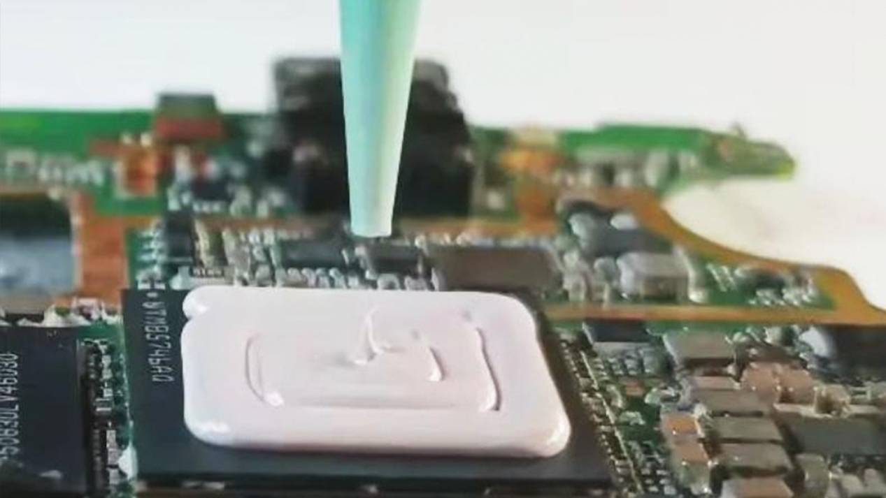
Solution: Employ a “central densification” dispensing pattern. For example, apply a dense grid or spiral pattern in the central area of the chip, and use sparse lines or dots in the edge areas. This ensures that more thermally conductive material is concentrated where it is most needed.
Common Patterns: Multi-row lines, grids, five-dot dispensing (four corners plus the center).
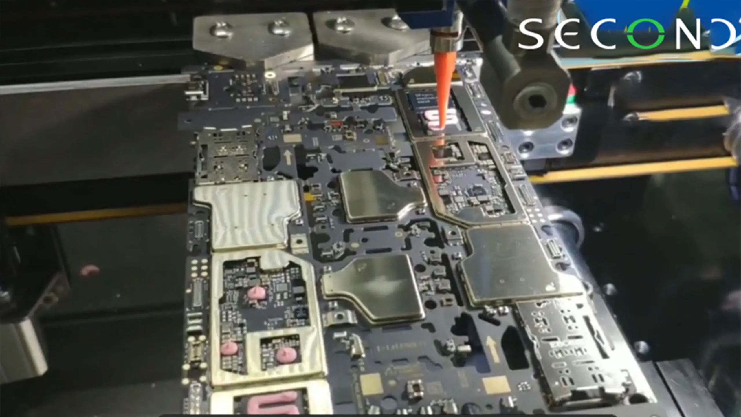
● Multiple Irregularly Shaped/Unequal Height Chips:
Problem: A PCB board may contain multiple heat-generating chips of varying sizes and heights. Traditional spacers are difficult to adapt.
Solution: Using 3D vision positioning and pressure control, the dispensing path and amount are independently programmed for each chip. Taller chips receive more dispensing, while shorter chips receive less, achieving “personalized” heat dissipation.
● Areas with Obstructions:
Problem: Capacitors, inductors, and other components may be present around heat-generating chips, potentially causing contact when the heatsink is pressed down.
Solution: The dispensing path can avoid these components, dispensing only in permissible planar areas, ensuring both safety and heat dissipation.
2.Process Parameter Optimization
● Adhesive Volume Control: Precise milligram-level control is achieved using a precision screw pump or pressure-time controller. Excessive adhesive volume leads to overflow and contamination, while insufficient volume creates hot spots.
● Dispensing Height and Speed: These affect the width and shape of the adhesive line. Optimization allows for the formation of ideal circular dots or uniform lines.
● Thermal paste selection: Choose thermal pastes with different thermal conductivity (e.g., 5W/mK, 8W/mK, 12W/mK or even higher) based on the required temperature rise of the hotspots. For extreme hotspots, top-grade thermal pastes containing phase change materials or metal fillers may be required.
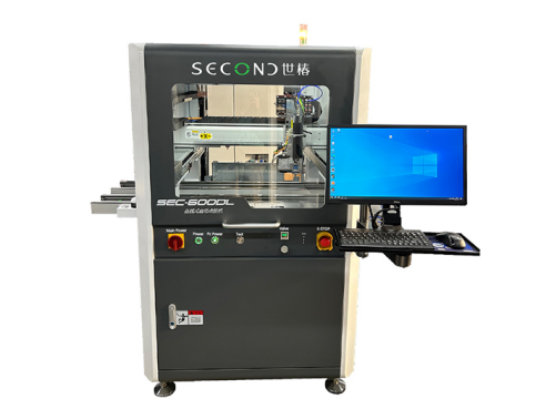
SMT automatic glue dispenser SEC-DH600L
Second Intelligent high precision smt automatic glue dispenser machine apply epoxy resin to the bottom of the PCB board for underfill
Second Intelligent smt automatic glue dispenser automation SEC-DH600L has the following advantages:
- CCD visual programming precise positioning, visual correction, improve programming efficiency and dispensing accuracy;
- Chinese and English operating system, the software interface layout is clear, the operation is simple, easy to learn and understand;
- Support visual inspection, integrated control of dispensing and visual inspection, multi-purpose machine, effective control of dispensing yield;
- It can be equipped with a lin e laser scanner for 3D path guidance and flexible dispensing;
- The software can support a variety of dispensing systems and functional module applications, such as automatic needle alignment, automatic
height measurement, dispensing weighing compensation, five-axis linkage and other functions, which can effectively overcome the difficulties of
various dispensing processes and help improve quality;
III. Application Cases
The following are several typical industry application cases:
Case 1: Data Center Server GPU Cooling
- Background: Training GPUs in AI servers consume extremely high power (e.g., 300W-700W), with the core area being the main hotspot.
- Challenge: Traditional application methods, under the pressure of the heatsink, easily cause the thermal paste to be squeezed outwards, resulting in insufficient thickness in the core area and excessively high junction temperature.
● Dispensing Solution:
1.Method: A high-precision automated dispensing machine is used to draw a “dense cross-grid” pattern on the GPU chip.
2.Material: High thermal conductivity (≥12W/mK) silicone grease or silicone-free thermal paste is used to prevent oil separation.
3.Effect: Ensures that the GPU core area is adequately covered with thermally conductive material of optimal thickness. Compared to manual application, the core temperature can be reduced by 3-8°C, significantly improving the stability and lifespan of the computing card.
Case Study 2: Automotive Electronic Power Module (IGBT/SiC) Heat Dissipation
● Background: IGBT or SiC power modules are used in the motor controllers and on-board chargers of new energy vehicles, requiring extremely stringent heat dissipation.
● Challenges: The modules are large, but the heat source is the multiple internal chips, requiring heat transfer to the water-cooling plate via the substrate. There is a risk of uneven installation pressure.
● Dispensing Solution:
1.Pattern: Employs a “multi-row parallel line” or “double X-shaped” dispensing pattern to ensure uniform coverage of the entire DBC/substrate area.
2.Process: Uses a feeding system with vacuum degassing function to eliminate air bubbles introduced during dispensing. After dispensing, the heat sink is pressed together in a vacuum environment to further remove interface air.
3.Results: Achieves an extremely low interface thermal resistance of less than 0.1K/W, ensuring the reliability of the power module under high temperature and high vibration conditions.
Case Study 3: Consumer Electronics Dispensing Smartphone SoC Heat Dissipation
● Background: Smartphone SoCs are the primary heat source, typically covered by a metal shield or vapor chamber (VC).
● Challenges: Extremely limited space, zero tolerance for adhesive overflow, and the need for rapid mass production.
● Dispensing Solution:
1.Pattern: Employs simple and efficient dispensing paths such as a “line” or “I-shaped” pattern.
2.Equipment: Uses an ultra-high-speed piezoelectric jet valve instead of traditional contact dispensing. It can non-contactly “jet” tiny adhesive dots, offering high speed, no stringing, and precise positioning.
3.Results: Dispensing is completed in milliseconds, perfectly adapting to production line rhythms and eliminating potential contamination from adhesive contact with the nozzle, resulting in extremely high yield rates.
1.Best Practices and Precautions
Surface Cleaning: Before dispensing, ensure the chip surface is clean, dry, and free of grease and dust.
Jig Design: The dispensing fixture needs to accurately position the PCB and consider the heatsink’s pressing guidance.
Process Monitoring: Introduce a vision system to photograph and check the shape, position, and quantity of the thermal paste after dispensing to ensure accuracy.
Material Management: Thermal paste often experiences settling issues; thorough stirring is necessary before use. The supply system should continuously and slowly stir to maintain uniform filler.
Coordination with Structural Design: Optimal heat dissipation requires coordinated design of the dispensing process with the heat sink structure, mounting pressure, and other factors.
Thermally Conductive Paste technology is an indispensable part of the heat dissipation design for modern high-performance electronic devices. By transforming a “one-size-fits-all” heat dissipation approach into a precise “data-driven, on-demand” heat dissipation solution, it effectively overcomes the hotspot problem, providing crucial support for the development of electronic devices towards smaller, faster, and hotter designs.
Second Intelligent has played an important role in theresearch, development, manufacturing, pre-sales and after-sales services of fluid dispensing robot, potting and coating solutions which range from various types of automatic fluid dispensing, potting, two-component potting machines and Conformal Coating Machine with desktop, free-standing, inline or cobot combined systems, and widely used in global electrical, electronics, home appliances, automobile, telecom, pharmaceutical, automotive electronics, semiconductor, aerospace, LED and more.