Overcoming the Dual-Valve Synchronized Dispensing Challenge: A Comprehensive Record of On-Site Problem Analysis and Optimization Solutions
In today’s rapidly advancing industrial automation, high-precision dispensing processes have become indispensable in fields such as 3C electronics and semiconductor packaging. However, when traditional dispensing systems face increasingly complex products and process requirements, a series of challenges emerge. This article aims to provide an in-depth analysis of five core problems encountered during a real-world on-site service case involving dual-valve synchronized dispensing equipment, along with proven solutions.
1.The Dilemma of Mechanical and Vision Calibration for Dual-Valve Synchronization
Problem Description:
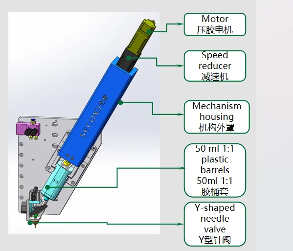
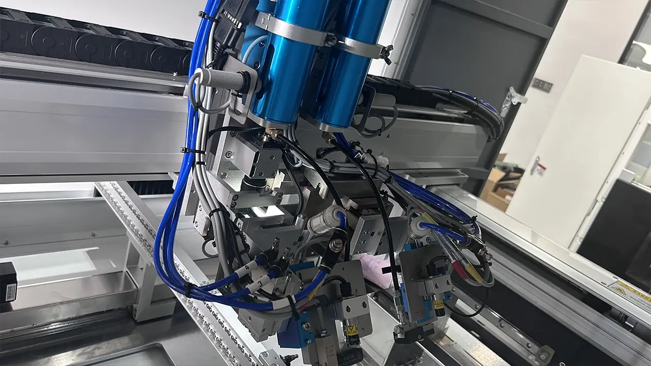
The dual valves used for synchronization are pneumatic, lacking control over angle and height, relying solely on manual visual alignment.
Pneumatic valves are cost-effective and responsive, but their inherent limitation is the lack of precise electronic control over angle and height. This leads to situations where, during collaborative dual-valve operations for parallel or complementary dispensing on the same product, the initial alignment depends entirely on the operator’s visual observation and manual adjustment, making it impossible to guarantee precision and repeatability.
Solution: Establish a standardized manual alignment process.
We developed a set of repeatable operating procedures:
Initial Positioning: Place the customer’s product on the dispensing platform fixture and bring the dispensing needle tips as close as the product as possible to minimize visual error.
Angle First: First, manually adjust the jetting angle of both valve bodies. It is essential to recognize that angle deviation directly causes distorted glue line trajectories or abnormal dot shapes, being the primary factor affecting dispensing quality.
Height Synchronization: After the angle is set, use glue dispensing valve 2 (with non-adjustable height) as the reference, and finely adjust the height of Valve 1 to ensure the lower end faces of both valve needles are at the same horizontal level.
Parallelism Verification: After completing the above mechanical adjustments, perform a test dispensing cycle (with air pressure or actual adhesive) and observe the landing points. Make fine adjustments again to ensure the parallelism of the adhesive discharge paths from both valves.
This process transforms reliance on individual “craftsmanship” into a standardized “process,” significantly improving debugging efficiency and consistency.
1.Prevention and Handling of Air Bubbles in Adhesive
Problem Description: After setting the parameters, dispensing works normally, but it’s unpredictable how long a cartridge of adhesive will last before bubbles appear.
Air bubbles in the adhesive are the “silent killers” of the dispensing process. They can cause unstable adhesive flow, inaccurate adhesive volume, breaks in the adhesive bead, and even affect product sealing and electrical performance. Especially in large-capacity (e.g., 300cc) cartridges, under continuous use and heating conditions, trace moisture or air in the adhesive expands when heated, and the negative pressure zone at the rear of the cartridge can easily lead to bubble formation.
Solution: Subdivision, Deaeration, and Active Purging.
Physical Subdivision: Divide the large 300cc packaging of adhesive into several smaller capacity tubes. This greatly reduces the exposure time of a single tube on the equipment, minimizing the opportunity for bubble generation at the source.
Vacuum Deaeration: Perform vacuum deaeration treatment on the subdivided adhesive. This is the most effective method for removing existing bubbles.
Warm-up Purging: Because the adhesive heating function is enabled, after replacing a new adhesive tube or restarting the equipment after a period of shutdown, the internal state of the adhesive is unstable due to temperature changes and settling. At this point, it is strictly forbidden to start production directly. The “Purge” operation must be performed first for 1-2 minutes to expel potentially unstable adhesive—with uneven temperature or containing bubbles—from the lines and valve body. Only begin production after the adhesive flow is stable and smooth.
III. Dynamic Shift: The Hidden Impact of Adhesive Volume Variation on Dispensing Position
Problem Description: The dispensing effect is unstable; the visual position shifts after regular intervals.
This is a highly deceptive problem. When an operator observes a shift in the dispensing position, the first reaction is often to adjust the vision system’s calibration or modify the dispensing path. However, through continuous observation, we found the root cause lies in the fluctuation of the actual dispensed adhesive volume itself.
Root Cause Analysis: As the remaining automatic adhesive dispenser in the cartridge decreases, the static pressure of the adhesive itself changes, and the resistance to piston advancement might also alter slightly. These factors collectively lead to a gradual decrease in the actual dispensed volume, even if the dispensing parameters (time, pressure) remain unchanged. When the adhesive volume decreases, the diameter of the adhesive dot or the width of the adhesive line shrinks, which visually appears as a “position shift.”
Solution: Process Control and Adhesive Volume Calibration.
Standardize Response Procedure: Strictly require the customer, upon detecting an abnormal dispensing position, to first perform a weight calibration of the dispensed volume instead of modifying the path.
Establish Monitoring Mechanism: Require hourly weight checks and recording of the dispensed volume from both valves. If the adhesive volume deviates from the standard range, immediately adjust the dispensing parameters (e.g., time, pressure) to correct it, thereby solving the so-called “position shift” problem at its root.
1.System Error: The Calibration Paradox of CCD and Tilted Valve
Problem Description: After calibrating the CCD and the needle tip, positional differences occur because the valve is tilted.
In vision dispensing systems, a CCD camera is typically used to accurately identify the dispensing position on the product, and then “hand-eye calibration” converts the visual coordinates into the robot motion coordinates. However, when the dispensing valve is installed at a tilt rather than vertically, a key variable—the dispensing height—is introduced into the equation.
Principle Analysis: During calibration, it is typically performed at a specific height (H1). But during actual dispensing, if the distance between the needle tip and the product (dispensing height H2) differs from H1, and because the valve body is tilted, the actual XY coordinates of the needle tip will exhibit an offset due to the height change. This offset cannot be ignored in applications requiring high precision.
Solution: A Choice Between Two Paths.
Option 1 (Root Cause Solution): Introduce a laser height measurement sensor. Before dispensing, measure the product surface height in real-time and dynamically adjust the robot’s Z-axis to ensure the dispensing height strictly matches the calibration height every time. This is a hardware-level solution that eradicates the problem and offers the highest precision.
Option 2 (Practical Solution): Abandon the complex calibration operation between the CCD and the tilted needle. After ensuring adhesive volume stability through weight checks, if a fixed offset in the path persists, directly use the “Coordinate Offset” function inherent in the robot system to apply a slight overall translational compensation to the entire dispensing path. The on-site technician ultimately adopted this solution because it is simple to operate, shows quick results, and is sufficient to meet the current product’s accuracy requirements.
1.Software Shortcomings: Exception Handling and Logic Optimization
Problem Description 1: The machine does not alarm when Valve 2 fails to reach the weighing position.
This is a typical safety hazard and software flaw. The equipment should have comprehensive soft limits and motion status detection functions.
Solution: Modify the control software (PLC or upper-level application) to add logic for judging whether Valve 2 has successfully moved to the weighing position. When the servo drive feedback is abnormal or a timeout occurs without reaching the position, the system should immediately trigger audible and visual alarms and display a clear error message on the Human-Machine Interface (HMI), preventing inaccurate weighing or dispensing in an abnormal state.
Problem Description 2: After dispensing on a product, the AB axes move to their set positions, causing interference when clicking “Move Valve 2 to Weighing Position”.
This is a logical conflict in the equipment action sequence design. The homing action after production completion interferes with the dedicated action used during maintenance.
Solution:
Fundamental Solution: Modify the software logic to define “Move Valve 2 to Weighing Position” as an independent action with the highest priority. When executing this command, the system should automatically check the current AB axis positions and plan a collision-free safe path to the weighing position, or force the AB axes to reset to a safe point before moving.
Temporary Workaround: Before the software modification, instruct operators to manually reset the machine or AB axes to the home position first when weighing is needed, and then execute the weighing command.
Summary
The problems encountered during this on-site service covered a wide range of aspects: mechanical structure, process materials, process control, system calibration, and software logic. This vividly demonstrates the challenges of high-precision dispensing systems as complex mechatronic products. By systematically organizing and solidifying these problems and their solutions, we not only resolved the customer’s immediate concerns but also helped them establish a sustainable process optimization system, ultimately achieving simultaneous improvement in equipment effectiveness and product quality.
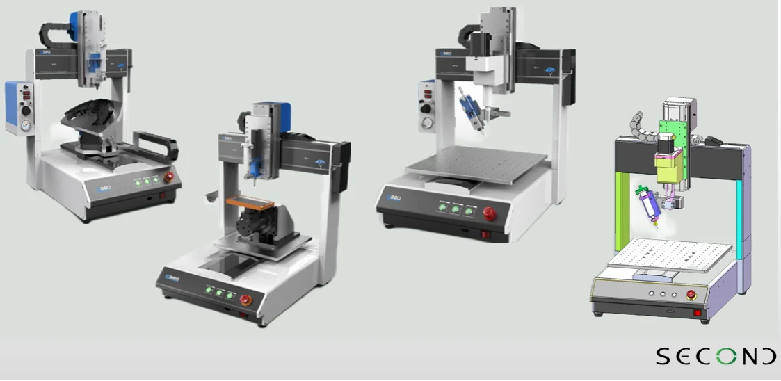
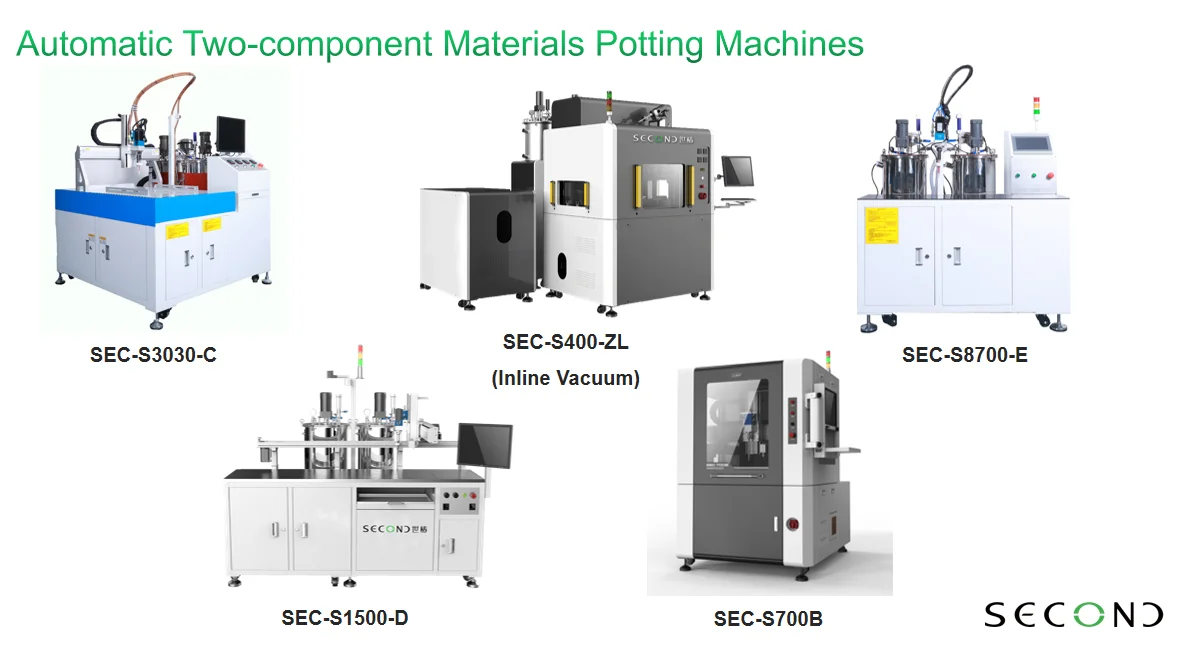
Second Intelligent has played an important role in theresearch, development, manufacturing, pre-sales and after-sales services of fluid dispensing robot, potting and coating solutions which range from various types of automatic fluid dispensing, potting, two-component potting machines and coating machines with desktop, free-standing, inline or cobot combined systems, and widely used in global electrical, electronics, home appliances, automobile, telecom, pharmaceutical, automotive electronics, semiconductor, aerospace, LED and more.